Posted: Sun Apr 03, 2005 11:31 pm Post subject: need help with controller port LEDs
ok i need some help putting LEDs into my contoller ports, and i am not too sure of how i should wire them. if some one could post me a lil tutorial on here with a diagram of how i should have them soldered on it would be helpfull.
thanks.
TheModGod Xbox-Hq Legendary
Joined: Apr 18, 2004 Posts: 5303 Location: Greensburg PA
Posted: Mon Apr 04, 2005 9:19 pm Post subject:
Okay, I know I have gave you some tips via PM, but I'll go ahead and post this tutorial. I know I have posted this before, but I guess you couldn't find it and I don't feel like digging. I know I had pics up, but I may not have had the complete process, so once I get this here I'll also turn it into a real tutorial. At the time I did this last we were unable to have images in our tuts, but now we are gold.
First off, I will not be held responsible for any damage you do to your machine while following these instructions. By opening your machine and working on it you are doing so at your own risk. I can only offer this information based on my own past experiences.
Tools Needed:
Wire cutters
Needle nose pliers
Precision Screwdriver
Mini Glue Gun and glue sticks
Electrical Tape.
Other Parts Needed:
3mm LEDs - at least 5000mcd (brightness rating)
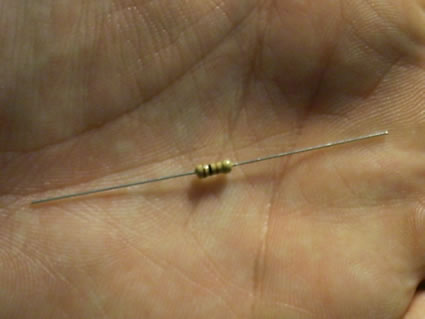
1/4 watt 100 Ohm Resistors.
Solder
15 watt soldering iron , try to get a pretty fine tip.
Desoldering braid and a 25 watt iron in case of goof up.
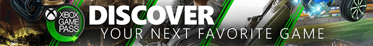
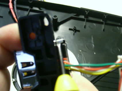
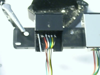
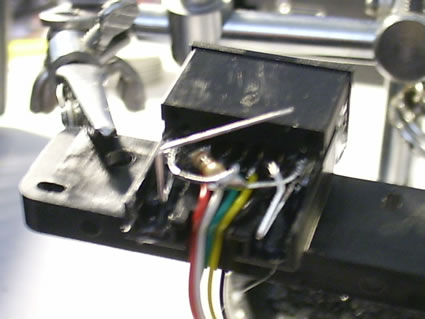
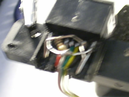
First, you need to open up the ports. To get the metal casing off I just use a small precision screw driver. The following two pics show how I manipulate the casing in order to pop it off.
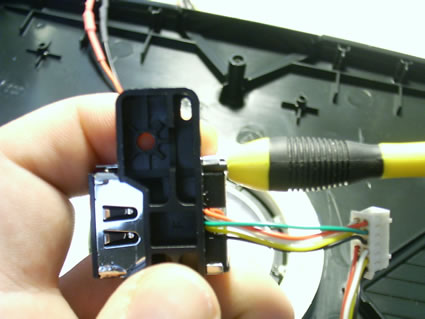
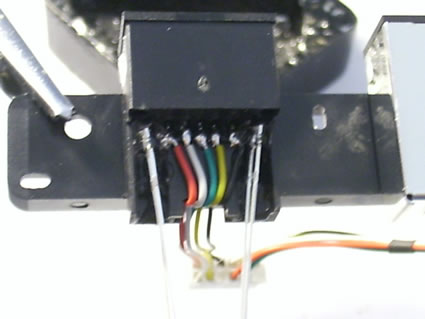
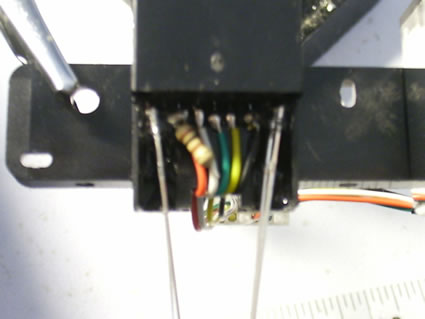
Now that you have it open, you will see the series of wires. Red of course is power and black is ground. I use helping hands to hold the ports in place while I work, but whatever you use is fine. At this point, I get my LEDs ready and prepare my resistors.
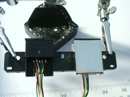
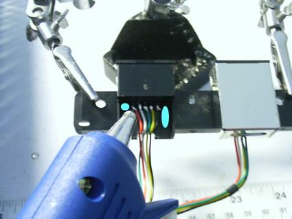
First, I place a little glue into the slots on the left and right side of the wires. I do one at a time so the glue doesn't harden before I can place the second LED. On the LEDs the longer leg is the positive, shorter is the negative.
Some people do not use glue. I prefer to use it, it's up to you. What I do is dip the LED into the glue and then push it into the crevice where the light eventually flows out of the front. This makes for a brighter mod rather than just gluing it down in place on the bottom of the port. I use compressed air to quickly cool the glue and move on to the second LED. You will end up with something that looks like this:
Ports in helping hands:
Laying down first bead of glue: (I made some small circles/ovals where the glue gets laid onto. Remember, just do one side at a time. I also make sure that the longer leg (positive is on top)
por
LED is now in place:
Both LEDs in place:
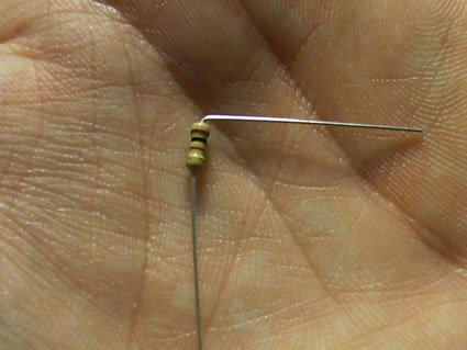
Now I prepare my resistor to solder in place. I take the resistor and bend one leg to a right angle.
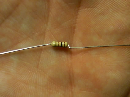
Before:
After:
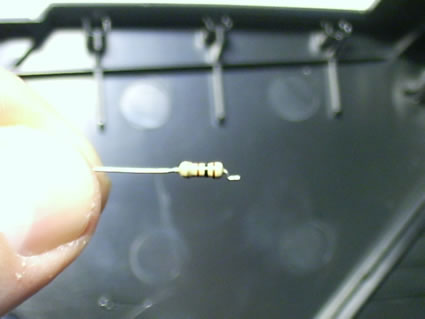
Next, I use my needle nose pliers to bend the already bent leg as shown in picture. This allws me to lay it down on the power wire and solder in place much easier than soldering and then bending like most tutorials call for.
After second bend:
After cutting off excess:
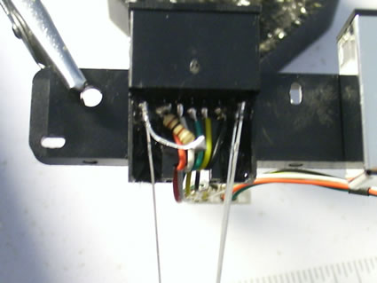
Now I solder the resistor into place and snip off excess leg of the resistor.
Next I bend the left LEDs positive leg to the top of the small leg of the resistor and solder in place. I then snip off the exceess resistor leg.:
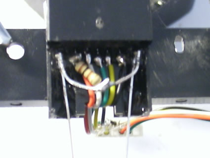
Next I bend the right LEDs leg to the underside of the small leg of the resistor and just heat up the solder that I did from the left leg. This will then solder the two LED positive legs together and make a sandwich so to speak of the resistor leg. This will give power nicely to both positive LED legs.:
Next, I take the negative leg on the right LED and bend it as seen in first picture. I then snip off a little bit of it. After I trim the leg slightly, I bend it again so it avoids the positive leg and can be soldered to the negative wire:
First bend and trim:
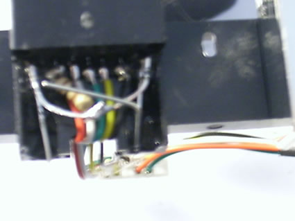
Second Bend and solder:
Next, I bend the negative leg on the left LED as seen in pics. Then I solder it in place as well, onto the ground wire. Then I make sure no positive and ground LED legs are touching, I place electrical tape over them and put the metal casing back on.
Left negative LED Leg Bend:
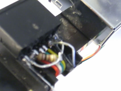
Left negative LED leg solder:
Some of the pics came out a little blury but I'll get better ones for the official tutorial. This is all I could do in a pinch.
Hope it helps.
TheModGod
--------------------------
http://www.themodgod.com _________________ Good Deals: Death@Hand, funkydopenloven, StaticMind, Slamscaper, PorscheXboxter
Bad Deals: None Yet
Pending Deals: Vanguard
funkydopeloven Xbox-Hq Genius
Joined: Nov 30, 2004 Posts: 1942
Posted: Mon Apr 04, 2005 11:04 pm Post subject:
hehe we need to spring for a digital camera with higher resolution for the ModGod
TheModGod Xbox-Hq Legendary
Joined: Apr 18, 2004 Posts: 5303 Location: Greensburg PA
Posted: Tue Apr 05, 2005 1:34 am Post subject:
No, it actually has the reso...it's just that I was too tired to d1ck around with the Macro lens settings...
It's a 4.1 megapixel _________________ Good Deals: Death@Hand, funkydopenloven, StaticMind, Slamscaper, PorscheXboxter
Bad Deals: None Yet
Pending Deals: Vanguard
funkydopeloven Xbox-Hq Genius
Joined: Nov 30, 2004 Posts: 1942
Posted: Tue Apr 05, 2005 2:07 am Post subject:
figured you had a decent camera :p M$ could trace you from your palm print in the resistor pictures.
TheModGod Xbox-Hq Legendary
Joined: Apr 18, 2004 Posts: 5303 Location: Greensburg PA
Posted: Tue Apr 05, 2005 2:51 am Post subject:
I used a hand model _________________ Good Deals: Death@Hand, funkydopenloven, StaticMind, Slamscaper, PorscheXboxter
Bad Deals: None Yet
Pending Deals: Vanguard
|
All times are GMT |Page 1 of 1
You cannot post new topics in this forum You cannot reply to topics in this forum You cannot edit your posts in this forum You cannot delete your posts in this forum You cannot vote in polls in this forum You cannot attach files in this forum You can download files in this forum